Quick Start Guide
DeviceTalk is an easy-to-use industrial software, it can be used for industrial data acquisition and visualization, it can also be used for devices' commissioning and maintenance. No programming is required for the user, and only need to configure it to start quickly.
For industrial devices with standard communication protocols such as Modbus RTU and Modbus TCP, the software provides the following features:
- Trend Display: Up to 24 signals can be displayed in real time for up to 2 hours;
- Trend Display: Each trace can be configured, and the trend can be easily manipulated, such as start, stop, pause, clear, etc.;
- Data Recording: Data can be saved, can be restored to display historical data and traces;
- Data Recording: Data can be exported in CSV format for external analysis;
- Device configuration: signal configuration, tree structure (device-group-signal), which can easily manage devices and signals;
- Signal Writing: Not only read, but also write the signal.
The following is a simple example to show how to use it.
Step 1: Modbus signal information of the device
The test software is a simple signal generator that generates sine and square wave signals and provides a communication interface (Modbus Server) for signal setting and real-time signal reading.
| Modbus Register | Name |
|---|---|
| 40101 | Sine Wave Actual Value |
| 40102 | Square Wave Actual value |
| 41001 | Sine Wave Enable |
| 41002 | Sine Wave Period |
| 41003 | Sine Wave Amplitude |
| 41004 | Square Wave Enable |
| 41005 | Square Wave Period |
| 41006 | Square Wave Amplitude |
40101 and 40102 are actual values for sine wave signal and square wave signal;
41001/41002/41003 are the enable, amplitude, and period settings of the sine wave signal;
41004/41005/41006 are the enable, amplitude, and period settings of the square wave signal.
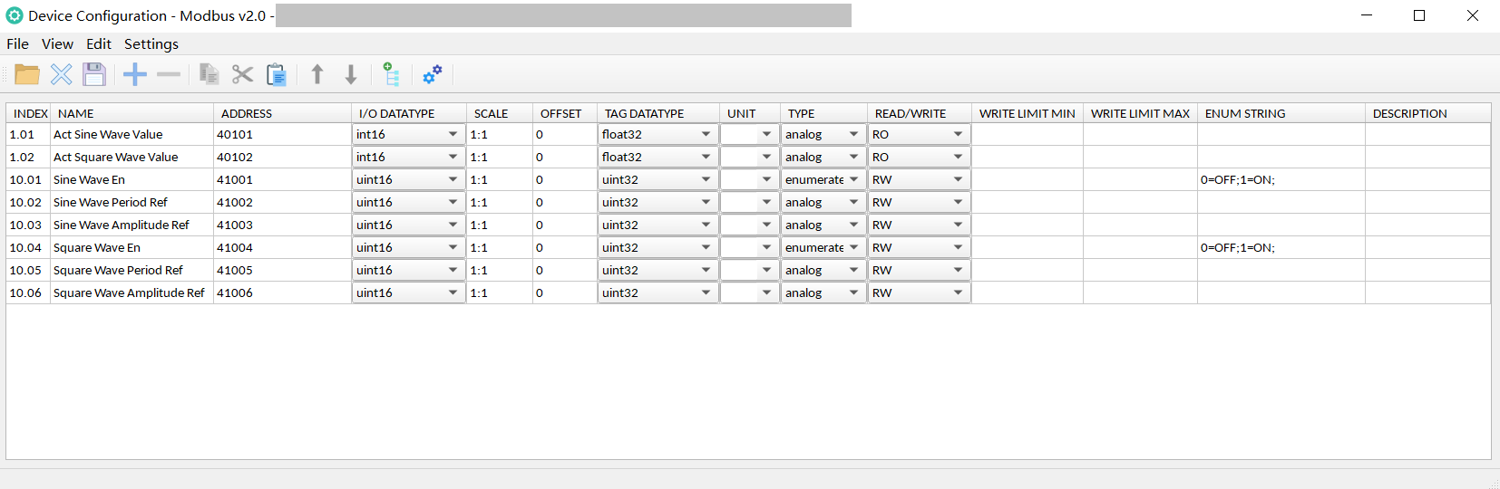
For each signal, it is also necessary to know the format of its communication value, the conversion method from the communication value to the actual value, the format of the actual value, the read/write property of the signal, and so on.
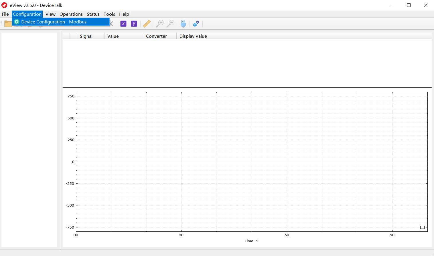
Step 2: Generation of the device configuration file
Click "Configuration" and then "Device Configuration - Modbus".
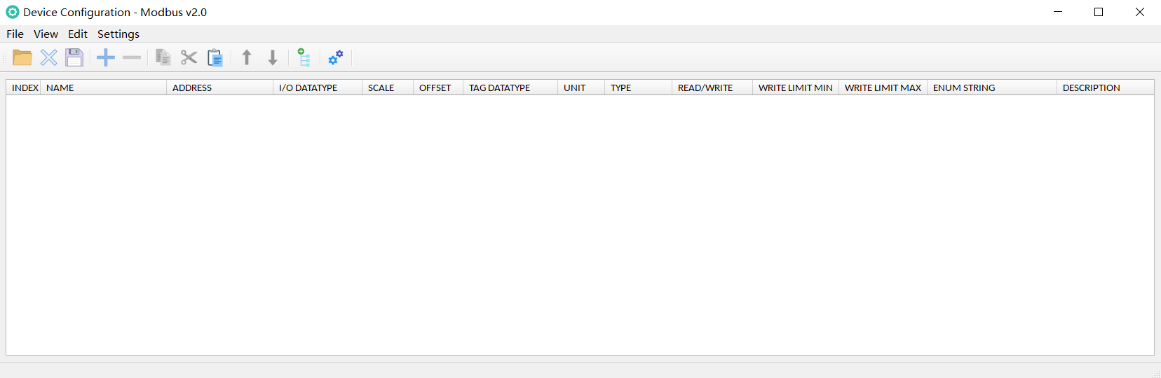
Next, setting the signal table, group, and settings in turn.
Signal Table:
Add rows in turn and set the signal as follows:
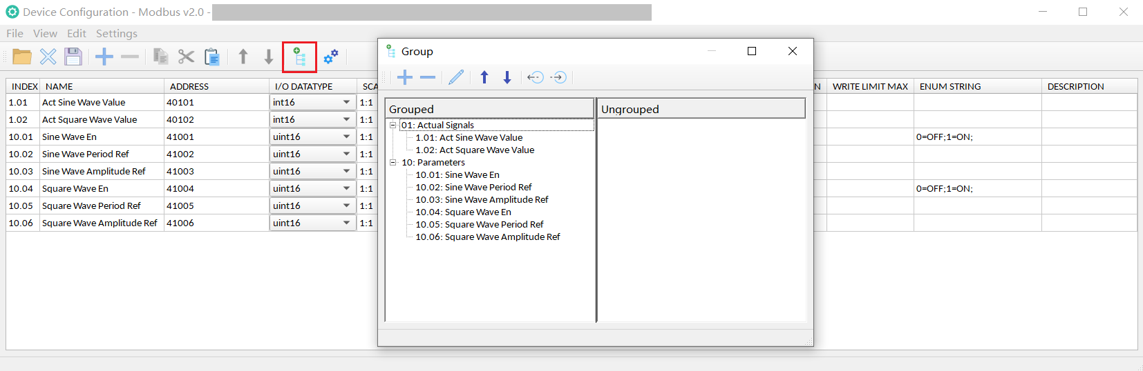
Group:
Grouping will facilitate the management of signals, and after grouping, a three-layer structure of "device - signal group - signal" will be formed.
Two groups are added, one is "01-Actual Signals" and the other is "10-Parameters", and then assign signals to these two groups.
Settings:
The user can enter the name of the device here, as well as the Modbus register related settings.
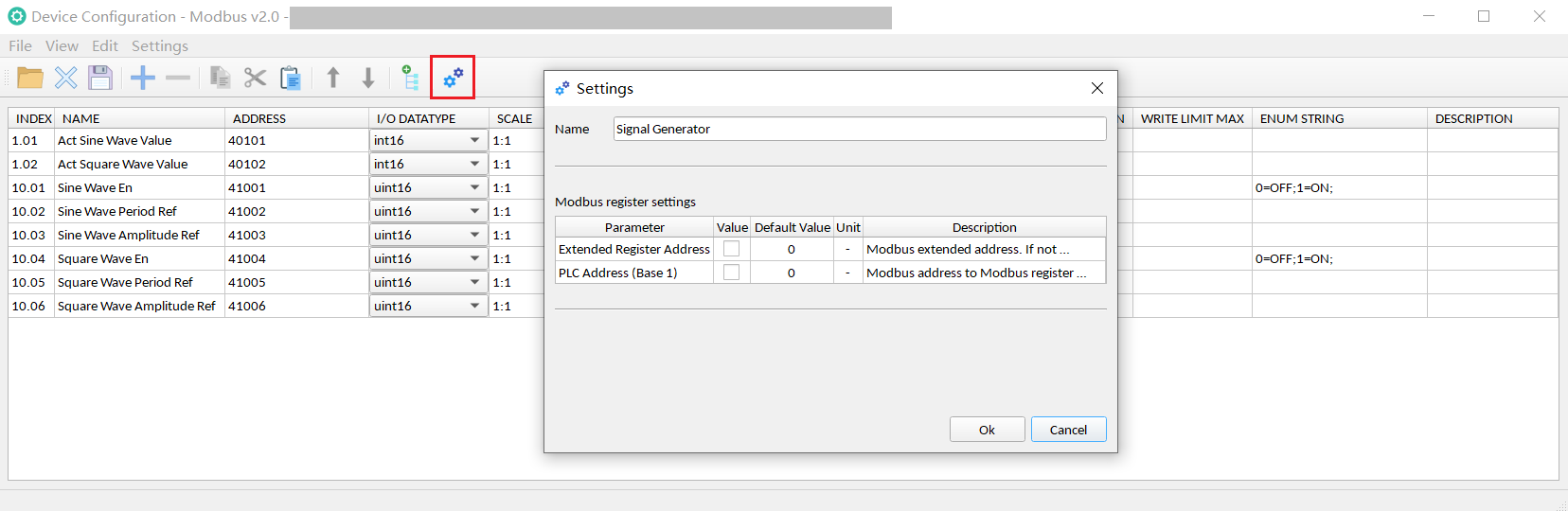
For example, Modbus register address of some devices has the offset( base 1), if there is an offset, user needs to check the box.
Save:
Save the settings as a file in .modpar format.
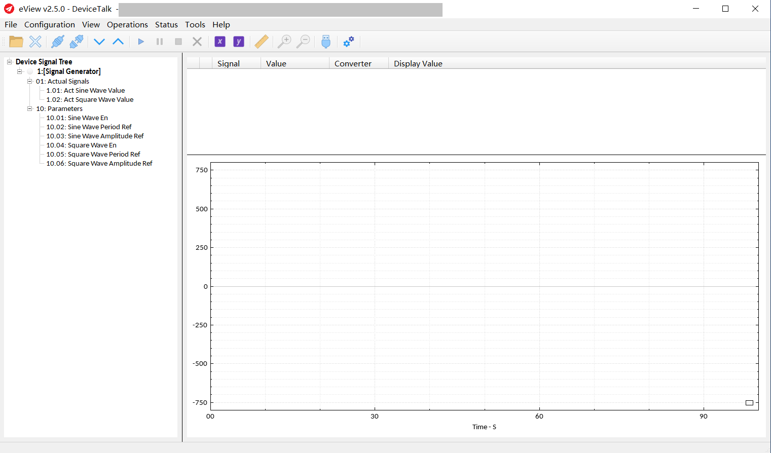
Step 3: Load and Use the Device Configuration File
Load .modpar File:
Open .modpar file
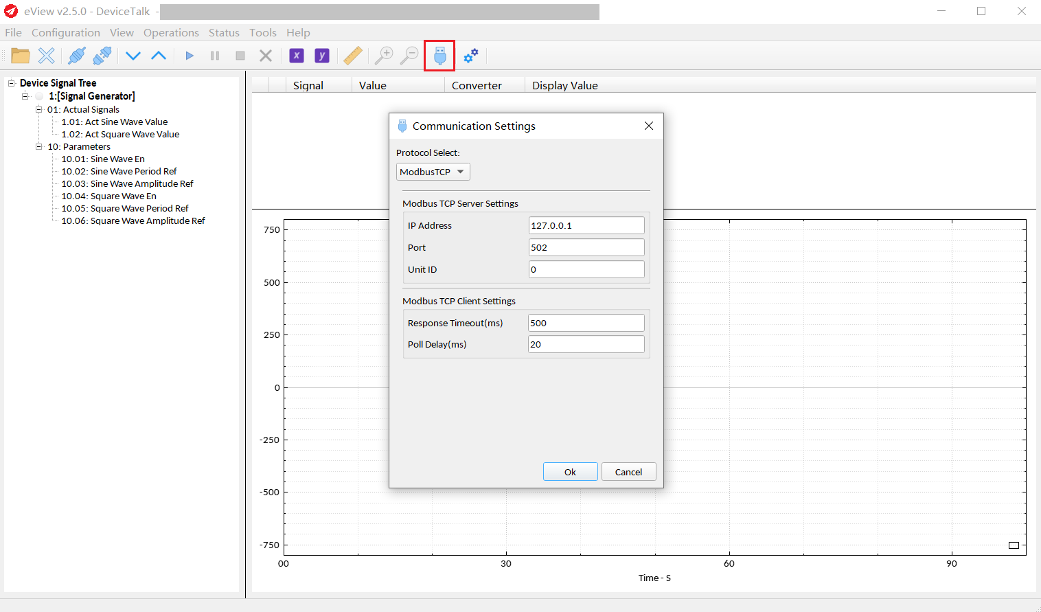
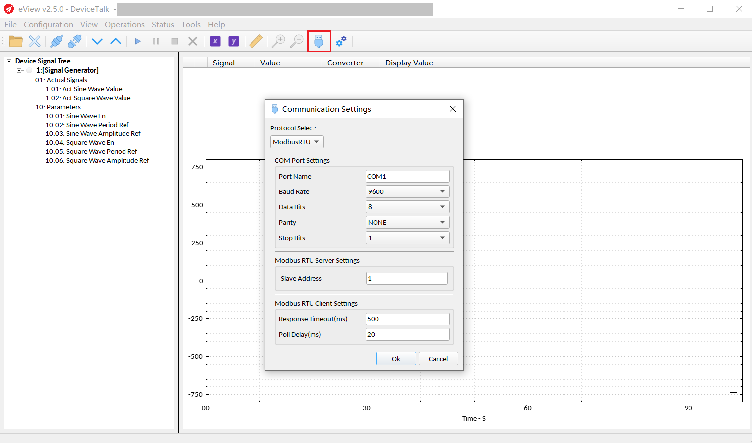
Communication Settings:
Click the Communication Settings button to enter the Communication Settings. Here, you can select the Modbus RTU or Modbus TCP protocol and set it up.
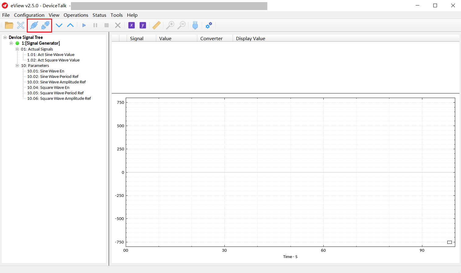
Connect and Disconnect:
Click the Connect or Disconnect button to connect or disconnect the device.
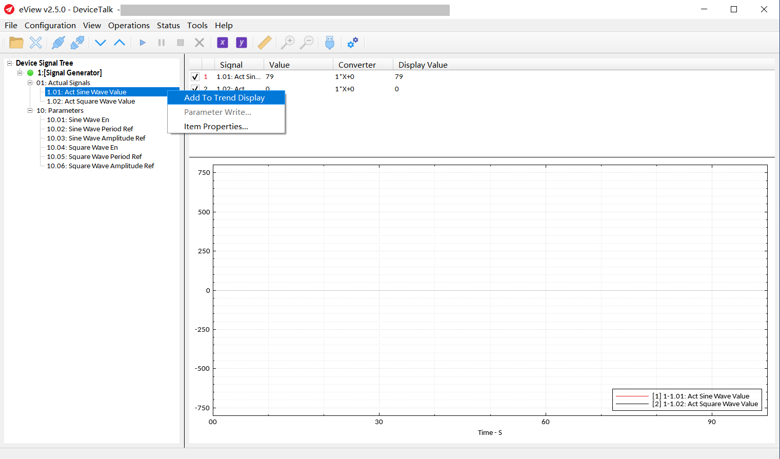
Add signal to the trend:
By double-clicking on the signal on the signal tree or by right-clicking and "Add to trend".
2 signals are added to the trend.
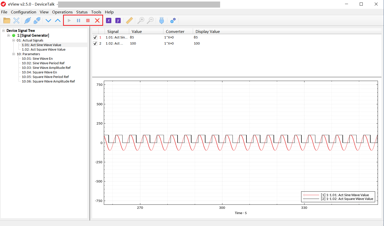
Trend:
Start, pause, stop and clear the trend can be controlled by clicking buttons “Plot Start”, “Plot Pause”, ”Plot Stop”, and ”Plot Clear”.
The X and Y axes can be set by clicking buttons “X-Axis Settings” and “Y-Axis Settings”.
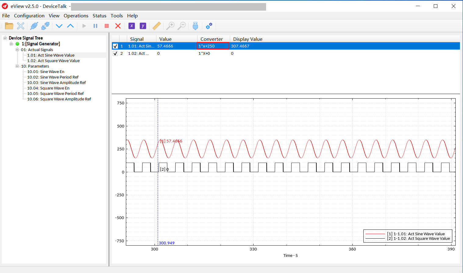
Usage of Marker:
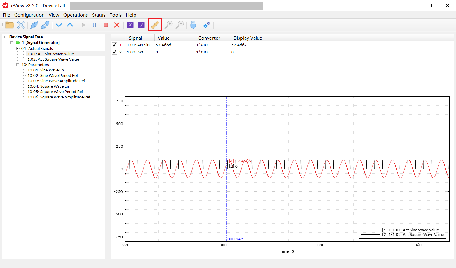
The user can adjust the position of the display position for each signal by “converter”, for example:
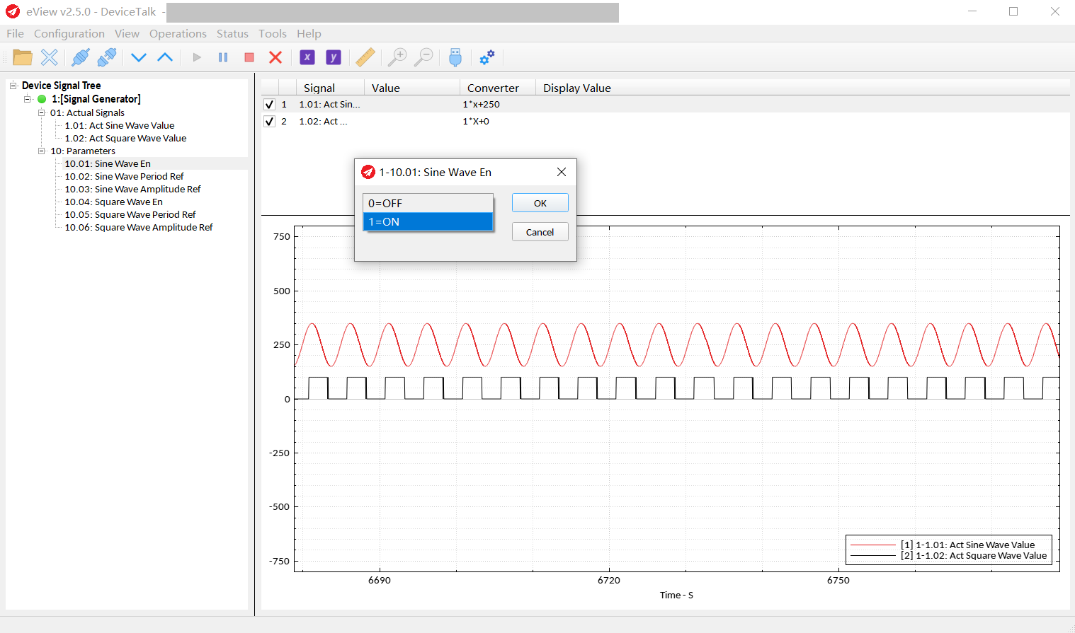
Signal Write:
Right-click the signal and select “Signal Write...", the dialog box for writing the signal will be displayed, and then you can edit the signal.
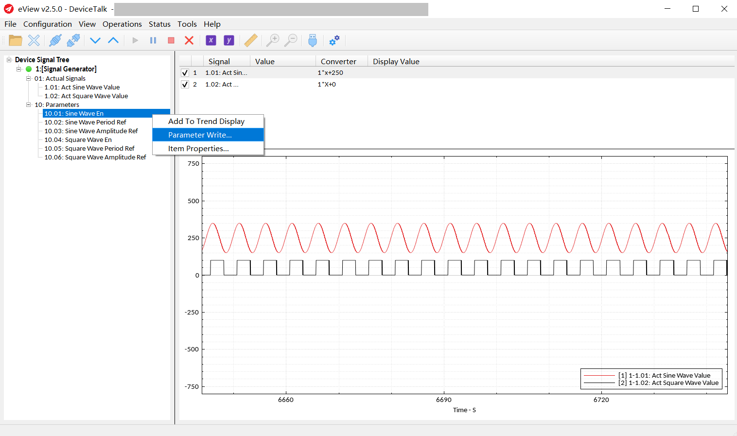
Usually this is a text editor. But if the type of the signal is enumeration, it will be a combobox for easy use.